A custom heat pipe heat sink is more than an aluminum heat sink with several copper tubes attached. Its performance depends on how well the heat source, heat pipes, base, fin stack, airflow, and mounting system work together.
That distinction matters. A heat pipe can transfer heat from a crowded hot spot to a larger cooling area, but it cannot make heat disappear. The condenser section still needs enough surface area and airflow to release that heat into the surrounding environment.
For engineers and sourcing teams, the design process should therefore start with the thermal problem—not with pipe diameter, fin count, or a drawing copied from an existing product.
What does a heat pipe do inside a heat sink?
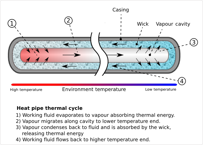
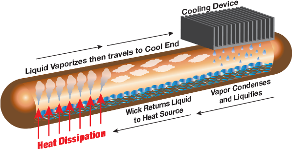
A heat pipe is a sealed, two-phase heat transfer device. Heat applied at the evaporator causes the internal working fluid to vaporize. The vapor moves toward a cooler region, condenses, and releases its heat. A wick structure then returns the liquid to the evaporator through capillary action.
The heat pipe normally has three functional zones:
- Evaporator: Receives heat from the electronic component or mounting base.
- Adiabatic section: Carries vapor between the hot and cold regions.
- Condenser: Transfers heat into the fins or another cooling surface.
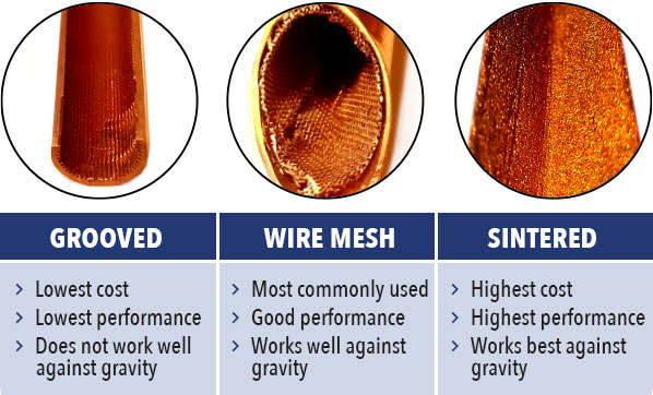
Common heat pipe assemblies for electronics use copper tubes, water as the working fluid, and an internal wick made from grooves, mesh, or sintered copper powder. The exact combination depends on operating temperature, heat load, orientation, geometry, and cost.
Here’s the thing: a heat pipe is not simply a piece of copper with very high thermal conductivity. Its effective performance changes with length, evaporator area, condenser area, heat input, wick design, and installation angle. Treating it as a fixed-conductivity material can lead to an inaccurate simulation or an undersized cooling system.
When should you use a heat pipe heat sink?
Adding heat pipes makes sense when heat cannot spread or travel efficiently through a conventional solid-metal base.
Typical situations include:
- The heat source is small, but the available fin area is much larger.
- The cooling fins must sit away from the electronic device.
- Several IGBTs, MOSFETs, processors, or power modules create concentrated hot spots.
- The product has a strict height or weight limit.
- A large aluminum heat sink shows an uneven base temperature.
- The far end of the fin stack contributes little to cooling.
- The mechanical layout blocks direct airflow over the heat source.
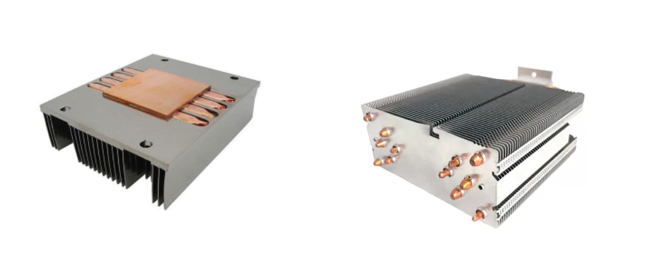
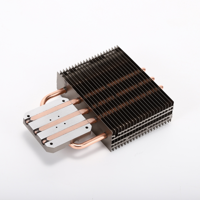
Heat pipes can also be embedded in an aluminum base to spread heat across a wider area. In this arrangement, heat does not move only from one end of the pipe to the other. It may condense along much of the pipe length as the surrounding heat sink removes energy.
Still, adding heat pipes to every design is not wise. If a standard extruded heat sink already meets the temperature target with a reasonable safety margin, the extra material, joining work, inspection, and assembly steps may add cost without delivering much practical value.
Step 1: Define the thermal design target
A statement such as “the component generates 300 watts” is not enough for custom heat sink design.
The engineering team should first define:
| Input | Information required |
|---|---|
| Heat load | Typical, peak, and transient power |
| Heat source | Quantity, dimensions, position, and spacing |
| Temperature | Maximum junction, case, or base temperature |
| Ambient condition | Minimum and maximum air temperature |
| Airflow | Natural or forced convection, flow rate, direction, and fan curve |
| Operating position | Horizontal, vertical, or variable |
| Space envelope | Maximum length, width, height, and keep-out zones |
| Environment | Dust, humidity, vibration, shock, altitude, and corrosion exposure |
| Service life | Expected operating hours and thermal cycles |
The first thermal estimate can use:
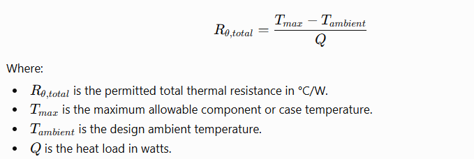
This is a starting point, not the complete answer. The thermal resistance between the junction, package, thermal interface material, heat sink base, heat pipes, fins, and air must all fit within the available thermal budget.
Step 2: Map the heat path
Before selecting a heat pipe, sketch the complete route that heat must follow:
Device → thermal interface material → mounting plate → heat pipe evaporator → condenser → fins → air
Each interface creates resistance.
For example, a capable heat pipe will not compensate for a poor contact surface beneath the power module. The same applies to an oversized fin stack placed in weak or recirculating airflow. One weak link can control the performance of the entire assembly.
During this stage, check:
- Contact area between the device and base
- Base flatness
- TIM type and compressed thickness
- Mounting pressure
- Distance between heat source and fin stack
- Contact area between the heat pipes and aluminum parts
- Available airflow through—not merely around—the fins
It’s a little like building a wide highway that ends at a narrow bridge. Improving the highway alone won’t solve the traffic jam.
Step 3: Select the heat pipe type and diameter
The heat pipe must carry the required power under the actual operating conditions. Selection should consider:
- Tube diameter
- Total length
- Evaporator and condenser lengths
- Wick structure
- Working fluid
- Operating temperature
- Gravity direction
- Number and radius of bends
- Flattened thickness, if applicable
- Heat input per pipe
Heat pipe capacity is not represented by one universal watt rating. It changes with geometry, temperature, orientation, and internal design.
Several physical limits may restrict heat transport, including viscous, sonic, entrainment, capillary, and boiling limits. In many electronics applications, the capillary limit becomes a major concern because the wick must return liquid to the evaporator.
For equipment that can operate in several positions, evaluate the worst-case orientation. A heat pipe may perform well when gravity helps return the liquid but lose capacity when the condenser sits below the evaporator.
A sintered powder wick is commonly considered when orientation flexibility and bending are important. Grooved structures may suit gravity-assisted designs, depending on the heat load and other conditions. Final selection should rely on supplier performance data and physical testing for the proposed geometry.
Step 4: Design the evaporator carefully
The evaporator must collect heat from the source without creating a local bottleneck.
Important design questions include:
- Is the evaporator long enough to receive the heat?
- Is the heat pipe centered over the hot spot?
- Does the base spread heat into all installed pipes?
- Will flattening reduce the pipe’s internal vapor space?
- Is the local heat flux within the selected pipe’s capacity?
- Does the mounting load risk crushing or deforming the pipe?
A larger contact area may lower local heat flux, but increasing base thickness is not always the right answer. A thick aluminum base adds weight and cost, while heat may still struggle to reach distant fins. Embedded heat pipes can sometimes provide better spreading with less material.
For high heat-flux devices, the base, TIM, and contact pressure deserve as much attention as the fin stack. A small chip can create severe spreading resistance even when total wattage appears manageable.
Step 5: Position the heat pipes inside the base or fin stack
Heat pipes may be:
- Press-fitted into machined grooves
- Bonded with thermal epoxy
- Soldered or brazed into compatible structures
- Clamped between machined plates
- Inserted through a fin stack
- Attached to a remote condenser block
The joining method affects thermal contact, strength, corrosion behavior, cleanliness, and production cost.
Groove geometry is especially important for embedded designs. Excessive clearance leaves an insulating air gap. Too much interference may deform the heat pipe. The drawing should define the groove profile, permissible gap, pipe location, and joining requirement.
Designers should also avoid tight bends near the evaporator or condenser unless the heat pipe supplier has confirmed the geometry. Bending and flattening can change the internal structure and reduce vapor-flow area. The minimum bend radius and permitted flattened thickness should therefore come from validated supplier data—not a generic rule copied from another design.
Step 6: Match the condenser to the fin stack
The condenser must transfer heat from the pipes into the fins with a low contact resistance. From there, the fins must release the heat into the air.
Fin design depends on:
- Fin material
- Fin thickness and height
- Fin spacing
- Air velocity
- Pressure drop
- Fin orientation
- Fin-to-pipe contact
- Air bypass and recirculation
- Dust accumulation and cleaning requirements
Dense fins provide more surface area, but they also increase pressure drop. With a weak fan—or natural convection—very tight spacing can reduce airflow and hurt performance. More fins do not automatically mean more cooling.
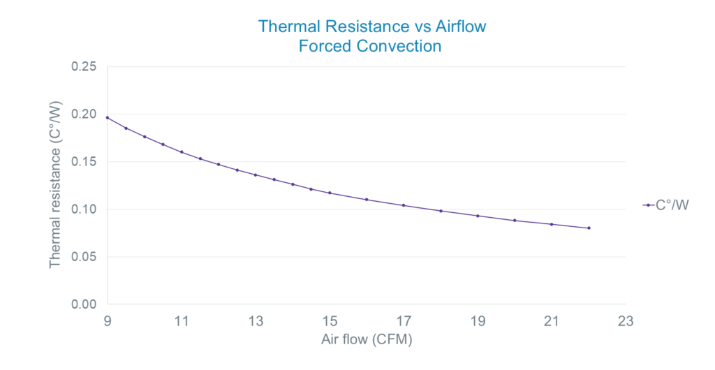
For forced-air systems, use the actual fan pressure-flow curve and estimate system resistance. Stating only the fan’s free-air flow rate can be misleading because airflow usually drops once the fan faces a restrictive fin stack, grille, filter, or enclosure.
Step 7: Consider mechanical and production constraints
A thermally strong design must still survive manufacturing, shipping, assembly, and field operation.
Review these points before freezing the drawing:
- Mounting-hole position and tolerance
- Base flatness after machining and assembly
- Heat pipe retention
- Fin deformation during handling
- Vibration and shock loading
- Galvanic corrosion between different metals
- Surface treatment requirements
- Electrical isolation
- Fan replacement and service access
- Packaging protection for thin fins
- Cleanliness requirements
Copper heat pipes combined with anodized aluminum parts also require thoughtful process planning. Anodizing chemicals and temperatures can affect how components are joined and when they should be assembled. In many cases, aluminum parts receive surface treatment before the heat pipes and temperature-sensitive components are installed.
The most suitable sequence depends on the construction and joining process.
Step 8: Simulate, prototype, and test
CFD and thermal simulation help compare design concepts, locate hot spots, and study airflow. However, the model must represent contact resistance, heat pipe behavior, TIM properties, fan performance, and boundary conditions with reasonable accuracy.
Physical testing should then check:
- Base or case temperature
- Temperature difference along each heat pipe
- Fin temperature distribution
- Inlet and outlet air temperature
- Airflow and pressure drop
- Fan speed and power
- Performance at maximum ambient temperature
- Worst-case installation angle
- Start-up and transient behavior
- Thermal cycling and vibration, where required
Thermocouples, thermal cameras, airflow instruments, and data loggers can help identify whether the limiting resistance sits at the device interface, heat pipe, condenser joint, fin stack, or airflow path.
A prototype that reaches the target temperature once is not enough. The test conditions and acceptance limits must be repeatable and documented.
Designing for production, not just for the prototype
A custom heat pipe heat sink must meet two goals: thermal performance and repeatable manufacturing.
KIMSEN Industrial Corporation supports custom thermal assemblies through aluminum extrusion, CNC machining, fabrication, welding, assembly, and inspection. Depending on the project scope, heat pipes and other specialized components may be sourced from qualified partners, while aluminum manufacturing, integration, assembly, and testing activities are organized around the customer’s technical requirements.
This production-led approach is useful for US and EU buyers who need more than a loose collection of parts. It allows the base, housing, mounting features, surface treatment, heat pipe integration, and inspection plan to be reviewed as one assembly.
Final takeaway
A successful custom heat pipe heat sink begins with a clearly defined thermal budget and a realistic heat-flow path. The heat pipe, base, joining method, fin stack, and fan must support one another.
Do not select a heat pipe by diameter alone. Do not judge a fin stack by surface area alone. And, perhaps most importantly, do not wait until mass production to confirm whether the assembly works at maximum ambient temperature and worst-case orientation.
Build the model. Make the prototype. Test the real assembly. That sequence may look slower at first, but it can save weeks of redesign once tooling and production fixtures are already in place.