A skived fin heat sink creates thin, closely spaced fins by cutting and lifting material directly from a solid aluminum or copper base. This process can place more heat-transfer surface area inside a limited volume than many conventional extruded profiles.
However, higher fin density does not automatically produce better cooling. Actual performance depends on whether the available airflow can pass through the fin channels, whether heat spreads effectively across the base, and whether the fin geometry remains manufacturable and mechanically stable.
For thermal engineers, the real design question is therefore not simply whether skiving provides more fins. It is whether the complete heat sink, fan, and enclosure operate together at a lower junction-to-ambient thermal resistance.
What Is a Skived Fin Heat Sink?
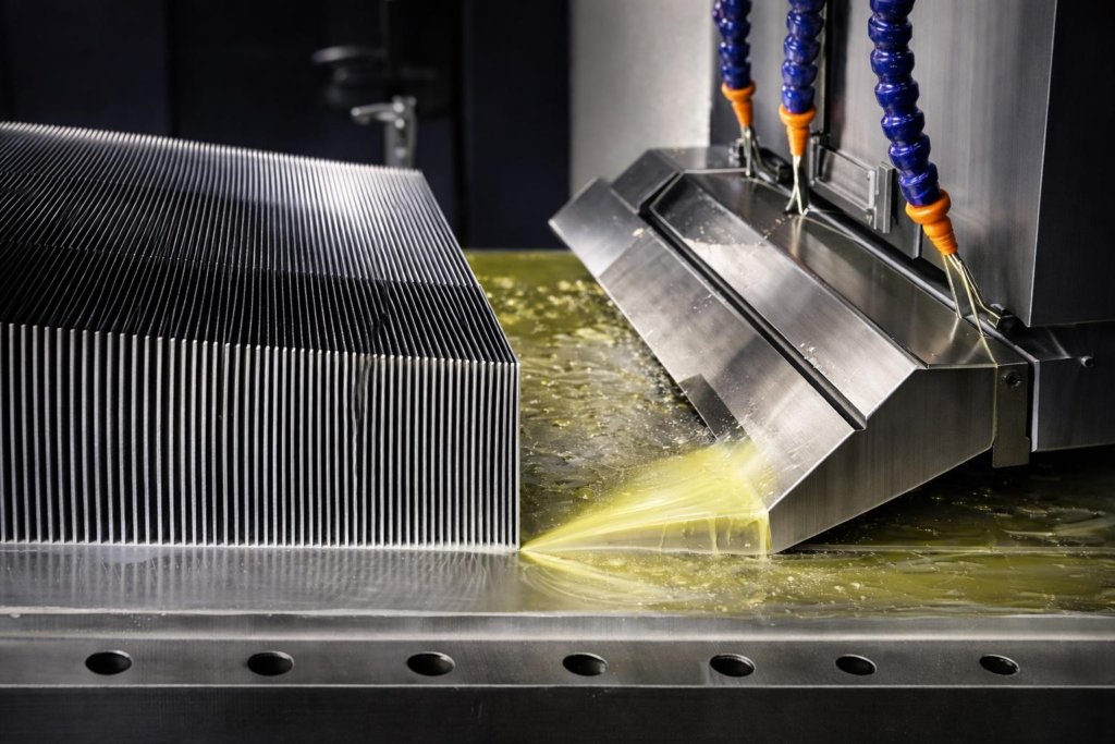
Skiving starts with a solid block or plate of thermally conductive metal. A controlled cutting tool enters the material at a shallow angle, removes a thin layer, and raises it into an upright fin. Repeating this motion produces an array of parallel fins that remain continuous with the base.
The process has three important characteristics:
- The fins and base form a one-piece structure.
- Fin thickness and spacing are not governed by the limitations of an extrusion die.
- Thin fins with relatively high aspect ratios can be produced in aluminum or copper.
Because no separate fin-to-base joint is required, a skived heat sink avoids the bond-line resistance associated with epoxied, soldered, or brazed fin assemblies.
This advantage should be described carefully because both skived and extruded heat sinks are normally monolithic. Skiving mainly differentiates itself from extrusion through its greater freedom to produce thin and densely arranged fins—not through the elimination of a joint that extrusion does not have.
Why Skiving Can Improve Cooling Performance
The purpose of a heat sink is to conduct heat away from a component and transfer it to the surrounding air. For a simplified plate-fin heat sink, the convective thermal resistance of the fin field can be expressed as:Rθ,conv≈h(Ab+ηfAf)1
Where:
- h is the convective heat-transfer coefficient.
- Ab is the exposed base area.
- Af is the total fin surface area.
- ηf is the fin efficiency.
Skiving can increase Af by fitting more fins into the same available width. However, the equation also shows why surface area alone is not enough.
If the fins become too tall or too thin, fin efficiency may decrease. If the gaps become too narrow, system airflow may fall, reducing the heat-transfer coefficient h. The effective surface area may then provide less improvement than the geometric area suggests.
This explains a common design mistake: selecting the highest possible fin count before evaluating pressure drop and fan performance.
Five Geometry Variables That Matter Most
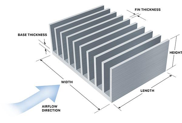
1. Fin Thickness
Thinner fins allow a higher fin count within a fixed heat sink width. They also reduce material mass and can increase surface-area density.
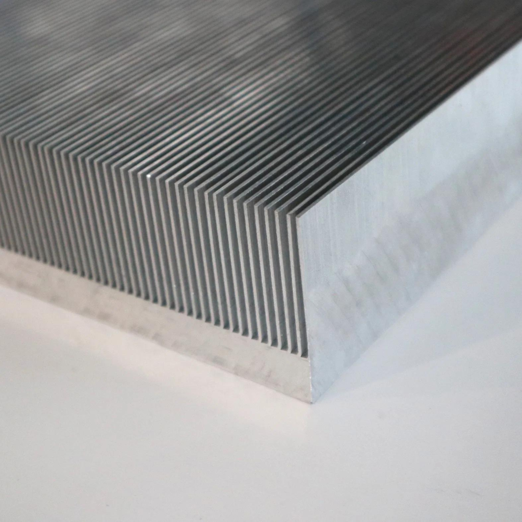
However, very thin fins have less cross-sectional area available to conduct heat from the base to the fin tip. Their efficiency decreases as the temperature gradient along each fin increases. Thin fins are also more vulnerable to deformation during:
- Manufacturing
- Handling
- Cleaning
- Surface treatment
- Transportation
- System assembly
The optimum fin thickness is therefore not necessarily the smallest dimension that a machine can produce. It is the smallest dimension that can still satisfy thermal, mechanical, manufacturing, and reliability requirements.
2. Fin Gap and Fin Pitch
The fin gap is the open channel between two adjacent fins. Fin pitch is normally the repeating distance from one fin to the next and includes both the fin thickness and the gap.
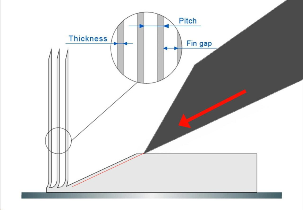
Narrower gaps allow more fins to fit within a fixed width, but they also increase airflow resistance. Under forced convection, the fan must generate sufficient static pressure to move air through the channels. Under natural convection, overly narrow channels can restrict the buoyancy-driven airflow needed to remove warm air.
Dust, coating build-up, and dimensional variation also become increasingly important as the gap decreases. A geometry that performs well in a clean laboratory may gradually lose cooling performance inside a dusty industrial enclosure if its channels become obstructed.
Fin gap must therefore be selected based on:
- Available airflow
- Fan static pressure
- Heat sink flow length
- Operating environment
- Surface treatment
- Manufacturing tolerances
- Cleaning and maintenance requirements
3. Fin Height
Increasing fin height adds heat-transfer surface area, but the improvement eventually reaches diminishing returns.
Heat must travel farther from the base toward the fin tip. As a result, the fin tip may operate at a temperature closer to the cooling air and contribute less heat transfer than the region close to the base.
Taller fins can also:
- Increase bending risk
- Require wider fin gaps
- Increase manufacturing difficulty
- Raise the total heat sink height
- Affect vibration resistance
- Increase pressure drop along the airflow path
The available fan pressure, enclosure height, mechanical environment, and fin efficiency should therefore be considered before maximizing fin height.
4. Airflow Length
Airflow length is the distance that air travels through the fin channels.
As air moves downstream, it absorbs heat and becomes warmer. Boundary layers also develop along the fin surfaces, while the longer flow path creates additional pressure loss.
A long heat sink may provide substantial geometric surface area, but the downstream section receives warmer air and may contribute less cooling than the upstream section.
For long airflow paths, engineers may need to:
- Review airflow distribution
- Divide the fin field into separate sections
- Use multiple fans
- Change the direction of airflow
- Reduce fin density
- Introduce heat pipes or a vapor chamber
- Improve ducting to prevent bypass and recirculation
The airflow direction should therefore be defined early in the design process rather than after the heat sink geometry has been finalized.
5. Base Thickness
The heat sink base must spread heat from the component footprint into the wider fin field.
If a small device applies a concentrated heat load to a large heat sink, an excessively thin base can create a strong temperature gradient. The fins closest to the heat source then carry most of the thermal load, while the outer fins remain underused.
Increasing base thickness can reduce spreading resistance, but it also adds:
- Material
- Weight
- Cost
- Overall height
- Vertical conduction distance
A thicker base is therefore not always the most efficient solution.
Heat pipes or a vapor chamber may provide better heat spreading when the heat-source area is much smaller than the available fin field, when heat flux is high, or when multiple concentrated heat sources must share the same heat sink.
Fin Density Must Be Matched to the Fan
The operating point of a forced-air cooling system occurs where the fan curve intersects the pressure-drop curve of the heat sink and the rest of the airflow path.
Adding more fins shifts the system resistance upward. A fan rated for high free-air flow may deliver substantially less airflow after it is connected to:
- Dense heat sink fins
- Filters
- Protective guards
- Ducts
- Enclosure openings
- Other internal components
This is why comparing heat sinks at the same nominal fan airflow can be misleading.
A reliable forced-air evaluation should consider:
- The pressure-drop curve of the complete airflow path.
- The fan pressure-flow curve at the intended voltage and speed.
- Air bypass around the heat sink.
- Inlet-air temperature.
- Hot-air recirculation.
- Airflow direction relative to the fins.
- Filter loading and expected dust accumulation.
- Acoustic and power-consumption limits.
For a dense skived fin array, a blower with stronger static-pressure capability may be more suitable than an axial fan with a similar free-air flow rating.
However, the final choice still depends on available space, acoustics, fan power, enclosure layout, and total system impedance.
Aluminum vs. Copper Skived Heat Sinks
Both aluminum and copper can be skived, but they address different thermal and mechanical requirements.
| Design factor | Aluminum skived heat sink | Copper skived heat sink |
|---|---|---|
| Thermal conductivity | Lower than copper and dependent on alloy | Higher, especially with high-conductivity copper grades |
| Density | Approximately one-third of copper | Significantly heavier |
| Material cost | Generally lower | Generally higher |
| Heat spreading | Suitable for many forced-air cooling systems | Better suited to concentrated heat sources |
| Mechanical impact | Lower load on mounting structures | Higher load on the PCB, frame, and mounting points |
| Surface protection | Anodizing or conversion coating may be used | Nickel plating may be used for oxidation protection or solderability |
Copper does not automatically make the complete heat sink more effective.
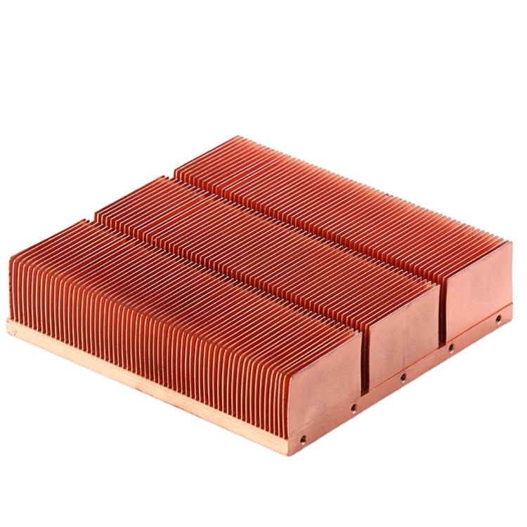
If convection from the fin surfaces is the dominant thermal resistance, replacing aluminum with copper may provide only a modest improvement at the system level while substantially increasing weight and material cost.
Copper becomes more valuable when conduction and spreading resistance are major limitations—for example, when:
- Heat enters through a small footprint.
- Heat flux is high.
- The available base area is tightly constrained.
- The fin volume is limited.
- Temperature uniformity across the base is important.
Material selection should therefore be based on the dominant thermal resistance rather than thermal conductivity alone.
Skived vs. Extruded, Bonded, and Zipper Fin Heat Sinks
Each manufacturing method occupies a different design space.
| Method | Main strength | Main constraint | Typical application |
|---|---|---|---|
| Skived fin | Thin, dense, one-piece fins without a profile die | Cycle time, flow-length limitations, and delicate fins | Compact forced-air cooling requiring high surface-area density |
| Extruded | Efficient production of continuous profiles | Fin thickness, gap, and aspect ratio are limited by extrusion | Cost-sensitive volume production with moderate geometry |
| Bonded fin | Tall fins and flexible base-fin combinations | Joint quality and additional assembly processes | Large heat sinks and high-aspect-ratio structures |
| Zipper or stacked fin | Thin sheet fins, low mass, and flexible module design | Requires attachment to a base, heat pipes, or vapor chamber | Fan-cooled modules requiring low fin mass and integration flexibility |
No manufacturing method has universally lower thermal resistance.
A valid comparison requires the following conditions to remain consistent:
- Heat sink footprint
- Material
- Heat load
- Heat-source size
- Inlet-air temperature
- Airflow boundary conditions
- Thermal interface material
- Mounting pressure
- Base temperature measurement position
An optimized extrusion may outperform an overly dense skived heat sink when airflow is limited. Likewise, a zipper fin module connected to heat pipes may outperform a one-piece skived heat sink when heat spreading is the dominant challenge.
How to Validate a Skived Fin Heat Sink
Computational fluid dynamics, or CFD, is useful for:
- Comparing design concepts
- Visualizing airflow distribution
- Identifying recirculation
- Locating hot spots
- Finding underused regions of the fin field
However, CFD does not replace physical testing, especially when performance is affected by fan behavior, thermal interface pressure, manufacturing variation, and enclosure leakage.
A practical thermal validation plan should control and report:
- Power input and measurement uncertainty
- Heat-source size and location
- Thermal interface material
- Interface-material thickness
- Mounting pressure or compression
- Inlet-air temperature
- Fan or blower operating point
- Airflow direction
- Duct configuration
- Sensor locations
- Sensor attachment method
- Steady-state acceptance criterion
- Base temperature distribution
- Pressure drop across the fin field
Heat sink-to-ambient thermal resistance can be reported as:RθSA=QTs−Ta,in
Where:
- Ts is the temperature measured at a defined heat sink reference location.
- Ta,in is the inlet-air temperature.
- Q is the heat transferred through the heat sink.
The reference temperature location must be clearly stated. A concentrated heat source can create a substantial temperature gradient across the base, so measurements taken at different positions may produce different thermal resistance values.
For production validation, dimensional inspection should be combined with functional testing. Relevant inspection items include:
- Base flatness
- Surface roughness
- Fin gap
- Fin height
- Fin straightness
- Bent or missing fins
- Burrs
- Cleanliness
- Coating coverage
- Mounting-hole position
These factors can affect both assembly and thermal performance.
Final Engineering Takeaway
The main advantage of a skived fin heat sink is geometric flexibility. Thin and closely spaced fins can be formed directly from the base, creating high surface-area density without a separate fin joint.
However, its actual thermal performance is controlled by the complete cooling system.
Fin count must be optimized together with pressure drop. Fin height should be balanced against fin efficiency and mechanical strength. Base thickness should be matched to the heat-source footprint. Material selection should depend on the dominant thermal resistance rather than conductivity alone.
The best skived heat sink is therefore not necessarily the design with the thinnest fins or the highest fin density.
It is the design that maintains the required component temperature at the actual fan operating point while meeting the system’s requirements for weight, noise, reliability, cost, and manufacturability.